
We will describe two versions of the invention, a cryocooler for use at very low temperatures and then a power generating air conditioning unit ( Figurere 4.)
Historical note:
This invention was the 1980’s precursor for Latent Power Turbines. At that time the need for a new type of refrigerator that did not damage the earth’s ozone layer was seen as even more urgent than fighting climate change. Hence Bill Courtney came up with the designs described below.
Bill’s financial aim in developing SALi Technology at Manchester University was to create funds to support the development of power generating refrigerators. However, when the Manchester University collaboration collapsed the design was radically simplified to save on research costs, resulting in the Latent Power Turbine design.
Cryocoolers
Our design can be used for very low temperature refrigerators or cryocoolers.
Here are some potential applications for a highly efficient parallel Stirling cryocooler:
(i) They could be used to cool power transmission cables to very low superconducting temperatures where there are no electrical resistance losses in the cables. (Currently, approximately 10% of all electricity generated is lost in the transmission process from supplier to consumer.)
As a bonus, burying superconducting cables underground is easier than burying conventional cables because there are no overheating problems to be solved.
(ii) Superconducting magnets would reduce heat losses in electric motors and generators.
(ii) They would reduce the running costs for magnetic traction rail transport systems.
(iv) Cutting edge physics.
Large capacity cryocoolers suitable for cooling nuclear particle accelerators are discussed in Section 4 below.
Throughout this article we will refer to our design as a “cryocooler” to emphasise these low temperature roles.
Looking for a research project?
Be the first to build a Parallel Stirling Cycle refrigerator!
In Section 6 we suggest a simplified version of the design for student project purposes.
1.1 The Parallel Stirling Cryocooler- How it works
Conventional refrigerators work by pumping heat out of a cold chamber,
raising it to a temperature above ambient, and then dumping it into the
environment as low grade heat.
Parallel Stirling cryocoolers and refrigerators are fundamentally different because they cool the working gas by forcing it to do external work.
We will start off with a diagram showing the main components, and then elaborate on the details.
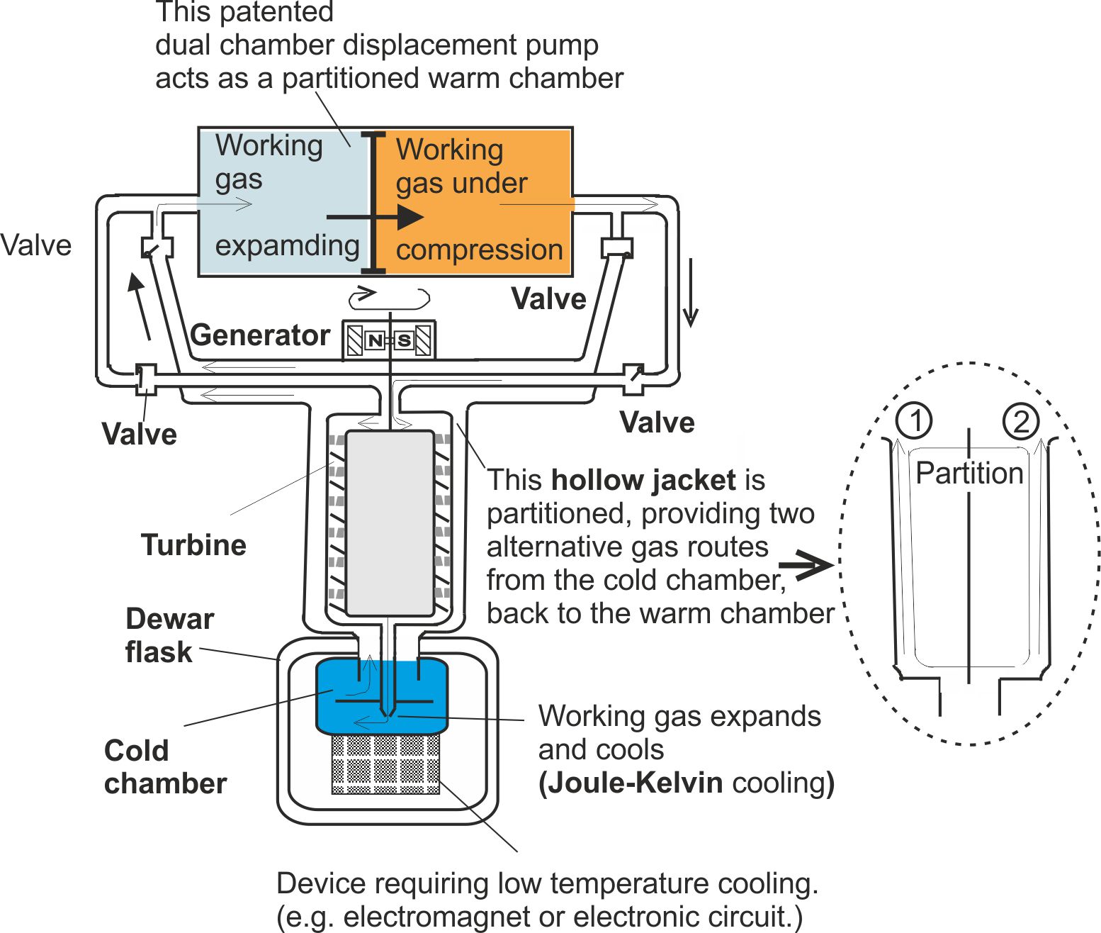
Fig. 1. Gas expansion and compression are happening simultaneously in different parts of the system.
In conventional Stirling refrigerator designs expansion and compression take place in sequence.
Below we reproduce the same diagram with brief explanations of how the main components work together.
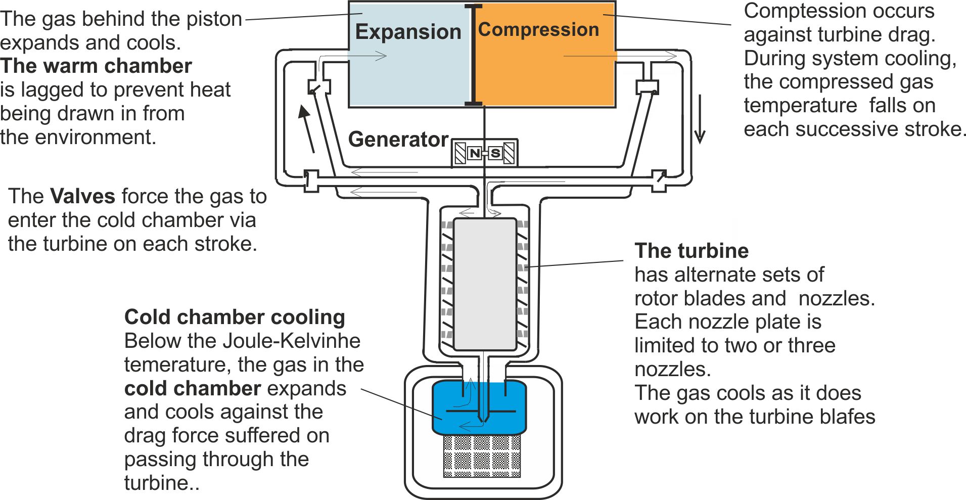
Fig. 2. Heat is extracted from the cold chamber and electricity is generated.
To a first approximation,
Rate of heat extraction = rate of electricity generation - rate of working against drag
The turbine unit consists of a series of sets of axial rotor blades, each set separated from its predecessor by a nozzle plate attached to the side walls.
The heat exchange mechanism
The pipe work and turbine chamber walls are made from aluminium alloy or other good thermally conducting metal. This allows the gas travelling from the warm chamber to transfer heat to the cooler gas passing back to the warm chamber via the jacket.
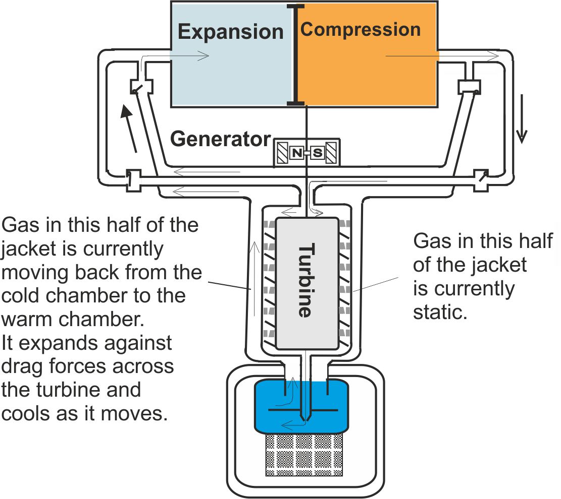
Fig. 3. The design offers heat exchange features. The two half jackets can be replaced by a single jacket and two exit valves. But this reduces the temperature drop caused by expansion because the total volume of gas expanding at any given time increases.
The gas travelling from the warm chamber to the cold chamber is subject to two cooling and two warming mechanisms, before it enters the cold chamber.
Cooling (i) Cooling due to external work being done, driving the turbine.
(ii) Cooling as heat is transferred to gas returning to the warm chamber.
Warming (i) Warming as the gas is compressed ahead of the piston.
(ii) Due to friction as work is done against drag.
Cooling caused by gas expansion is useful because it increases temperature gradients and hence rates of heat flow. It does not produce significant net cooling because expansion in those parts of the system behind the piston is offset by compression ahead of the piston.
Design notes
(i) Bends in the return pipes are reduced to a minimum at the expense of sharper bends for lines entering the cold chamber. This minimises the expansion of the gas against drag and ineffective cooling after the gas has left the cold chamber.
(ii) The output from the warm chamber can be split, with half passing through the turbine and half passing through one of two jet pumps (one for each half cycle) immediately on exiting the cold chamber. These jets will accelerate the flow of gas exiting the chamber and convert the current return side of the warm chamber from an extraction pump into a into a displacement chamber. This means that no cooling occurs in the warm chamber, lifting the mean temperature of the warm chamber and allowing it to dissipate heat into the environment.
(iii) The power output can be smoothed by increasing the moment of inertia of the turbo-generator.
(iv) The power output can also be smoothed by employing two dual chamber displacement pumps operating out of phase by 90o.
(v) Suitable dual chamber displacement pumps are described in patents GB 2273133 and GB2306580 and summarised on this linked webpage.
1.2 A power generating air conditioning unit
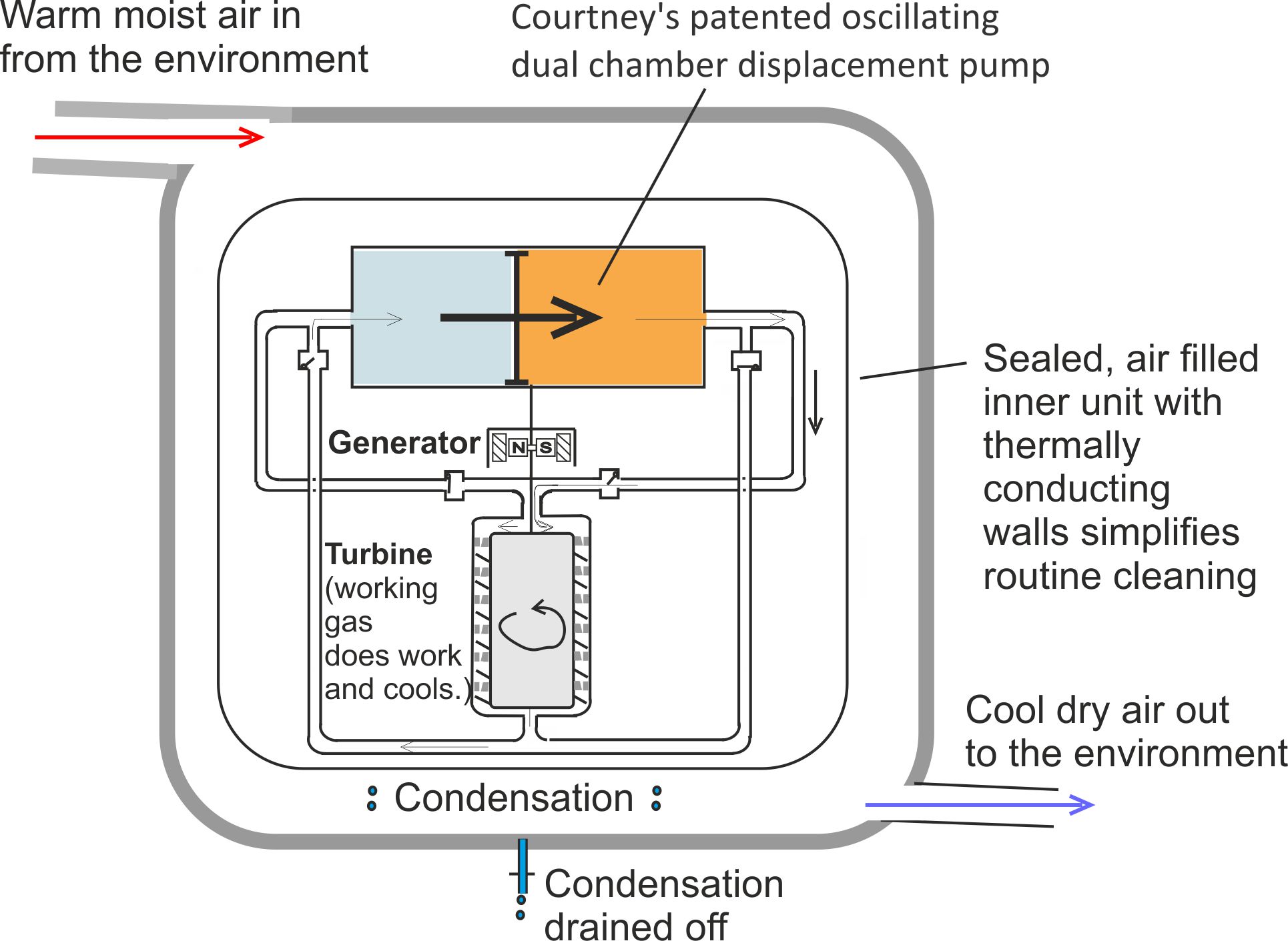
Figure 4. For air cooling purposes the design is simplified by removing the cold chamber.
2 Examples of basic dual chamber pumps for research purposes
2.1 A simple pump based on existing loudspeaker designs.

Fig. 5. An oscillating piston partitions the warm chamber. Two motors drive the piston, these being essentially powerful moving coil loudspeaker type motors. Armature coils mounted centrally, one on each side of the piston carry alternating currents. These act in harmony, causing the piston to oscillate to and fro, between two pot shaped permanent magnets.
2.2
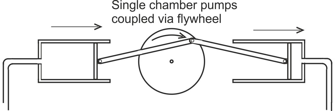
Fig. 6. Two single chamber pumps operating in anti-phase can simulate a dual chamber pump.
2.3 For dual chamber pump designs offering lubricant free action suitable for cryogenic applications please visit our Lubricant free pump page.
3 The turbo-generator unit: A magnetic bearing design for cryogenic temperatures
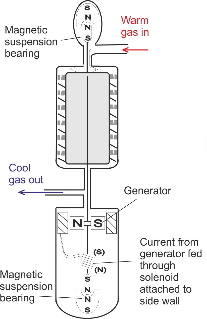
Fig. 7. The coil draws its current from the turbo-generator, so the coil’s magnetic attraction for the underlying bar magnet varies in step with the rate at which gas is pumped through the turbine.